A Wearable Synthesiser
Physical Computing
The biggest problem with modern music production software and device building is the lack of intuitive control and sensory feedback between user and computational device. Although commercially successful devices such as Novations ‘LaunchPad’ and Korg’s plethora of devices claim to be intuitive to use, they (and the rest of the market in such devices) tend towards presenting the control and sequence of musical data in a linear fashion, or in a traditional tone-chromatic keyboard style. Consequently, most users suffer a ‘trade-off’ in the form of a loss of immediacy between their desired result in their head and the result which is ultimately realised through the device.
To combat this problem, the solution I offer up to potential users is to make use of the most fundamental of our desires – to move. Constructing the synthesiser out of wearable clothing, working in symmetry with the user, rather than pushing against them.
Stage 1 – Sketches and design
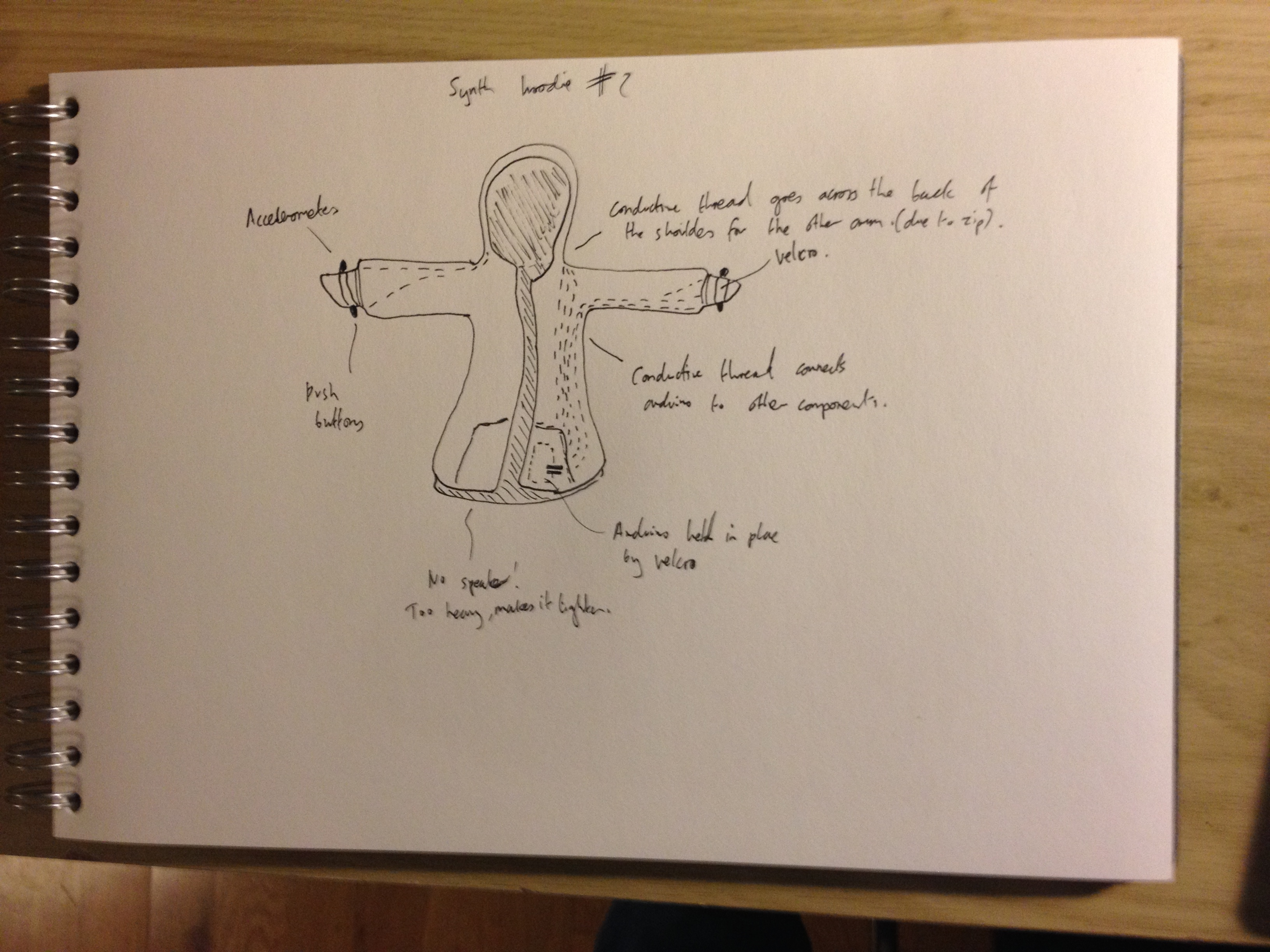
The first stage of the project was to sketch out design ideas of what the project might look like, and how it could work. I settled with using a hoodie for the choice of clothing as it was unisex, comfortable and in most cases came with a front pocket suitable for potentially housing electronic components.
I drew up two potential designs, settling on the second. However both designs followed the same main principles, in terms of how the device would work within them.
Using two accelerometers (one on each wrist) and two pushbutton arrays (two on one wrist, three on the other, placed on the underside of the wrist) connected to an Arduino Nano via conductive thread the user would be able to intuitively draw their desired waveform with one hand and control pitch with the other. The two button array would be used to control turning the ‘wave draw’ function of the synthesiser on and off, as well as the ‘signal/audio out’ on or off. The three buttons on the other wrist would be used to select between three different channels, allowing the user to save multiple sounds and to switch between them quickly. I also wanted all the electronic components housed in fabric pockets attached to velcro so they could be removed from the hoodie allowing it to be washed or worn as an ordinary item of clothing.

The first design.
The second design, which I would end up using.
The only notable difference between the two designs was that the first contained a speaker mounted in the front pocket. Although this would’ve been a nice feature I decided it would be too heavy for the hoodie and end up rather uncomfortable .
To begin with I ideally hoped all the software used for the synth would be housed on the Arduino chip itself, meaning only an audio jack out would be needed, making the device almost completely wireless. However as I was unsure with the quality and ease of how I would go about achieving this the backup plan would be to use the serial out from the Arduino via USB into Cycling 74s MaxMSP.
The final design factor would be that the device had to be built on a budget equivalent of a shoes string, and I also hoped that if I could work out some of the design bugs, in terms of how it would function, I could then use it as a proof of concept for a commercial product.
Stage 2 – Parts, testing and soldering
The next step was to purchasing all the necessary components I would need. After a week of hunting around trying to determine what parts I thought I needed I and where I could get them the following parts were purchased:
£23.88 2x Adafruit Triple 3-Axis Accelerometer ADXL335
£8.90 1x Arduino Nano
£3.17 100(!)x 6mm by 4mm Panel PCB Momentary Push Button Switch (cost effective!)
£6.96 1x 76ft Adafruit Stainless Thin Conductive Thread 2 ply
£14.95 Mens Medium Brave Souls Hooded Zip Jumper
£1.39 Velcro 3m (allegedly, only came out to 1m when I actually got it).
Additionally I also used many feet of wiring (some of which was kindly donated to me by fellow student Angie Fang, and some strip-board donated by fellow student Matthias Moos as well as five 10k Ohm Resistors which I already owned.
Total cost (excluding kit purchased for class) was £59.25.
After an additional week of waiting for the parts they finally all showed up!

Arduino Nano, length smaller than that of a match!
Once I had received the accelerometers I tested them to see if they worked. I did this by connecting the ‘vin’ pin of the accelerometer to the 5V of the Arduino, the ground pin to the Arduino’s ground and the accelerometers ‘3vo’ pin to the ‘aref’ pin of the Arduino. I then connected the X, Y, and Z pins to the first 3 analog pins of the Arduino (A0, A1 and A2 respectively). I then ran the following code and checked the serial monitor for input, which eventually showed it was working correctly (once I had finally put everything in the right pin!). The following code was used to do this:
//right hand
const int ap1 = A0;
const int ap2 = A1;
const int ap3 = A2;
//left hand
const int ap4 = A3;
const int ap5 = A4;
const int ap6 = A5;
//————————————-//
//right hand x
int sv1 = 0;
int ov1 = 0;
//right hand y
int sv2 = 0;
int ov2 = 0;
//right hand z
int sv3 = 0;
int ov3 = 0;
//————————————-//
//left hand x
int sv4 = 0;
int ov4 = 0;
//left hand y
int sv5 = 0;
int ov5 = 0;
//left hand z
int sv6 = 0;
int ov6 = 0;
//————————————-//
void setup() {
// initialize serial communications at 9600 bps:
Serial.begin(9600);
}
void loop() {
//connect 3.3v to AREF
analogReference(EXTERNAL);
// read the analog in value:
sv1 = analogRead(ap1);
// map it to the range of the analog out:
ov1 = map(sv1, 0, 1023, 0, 255);
//
delay(2);
// read the analog in value:
sv2 = analogRead(ap2);
// map it to the range of the analog out:
ov2 = map(sv2, 0, 1023, 0, 255);
//
delay(2);
// read the analog in value:
sv3 = analogRead(ap3);
// map it to the range of the analog out:
ov3 = map(sv3, 0, 1023, 0, 255);
//
delay(2);
// read the analog in value:
sv4 = analogRead(ap4);
// map it to the range of the analog out:
ov4 = map(sv4, 0, 1023, 0, 255);
//
delay(2);
// read the analog in value:
sv5 = analogRead(ap5);
// map it to the range of the analog out:
ov5 = map(sv5, 0, 1023, 0, 255);
//
delay(2);
// read the analog in value:
sv6 = analogRead(ap6);
// map it to the range of the analog out:
ov6 = map(sv6, 0, 1023, 0, 255);
//
delay(2);
//————————————-//
// print the results to the serial monitor:
Serial.print(“Xsensor1 = “ );
Serial.print(sv1);
Serial.print(“\t output1 = “);
Serial.println(ov1);
Serial.print(“Ysensor1 = “ );
Serial.print(sv2);
Serial.print(“\t output2 = “);
Serial.println(ov2);
Serial.print(“Zsensor1 = “ );
Serial.print(sv3);
Serial.print(“\t output3 = “);
Serial.println(ov3);
Serial.print(“Xsensor2 = “ );
Serial.print(sv4);
Serial.print(“\t output1 = “);
Serial.println(ov4);
Serial.print(“Ysensor2 = “ );
Serial.print(sv5);
Serial.print(“\t output2 = “);
Serial.println(ov5);
Serial.print(“Zsensor2 = “ );
Serial.print(sv6);
Serial.print(“\t output3 = “);
Serial.println(ov6);
//Only output every second so it’s easy to read if its working or not.
delay(1000);
}
After a successful test I began to solder (for the first time!) the parts to their respective strip-boards, using chopped female to male wires so they could be detached to and from the hoodie as required by the design brief I laid out.
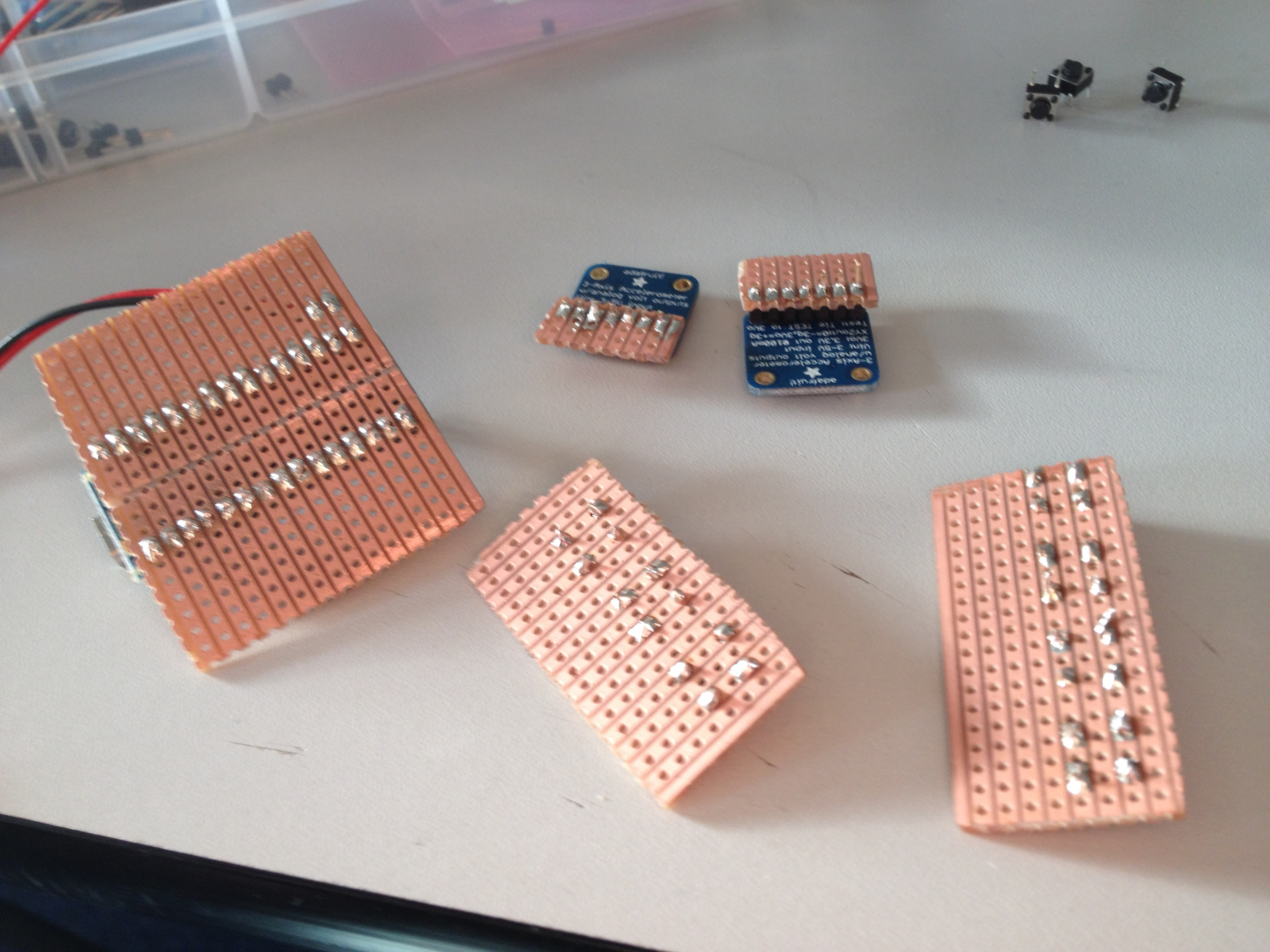
Undersides of all the separate boards and components.

2 Pushbuttons with a 10k Ohm Resistor for each (the same was done for the 3 buttons too).

Most of the soldering down for the separate boards.
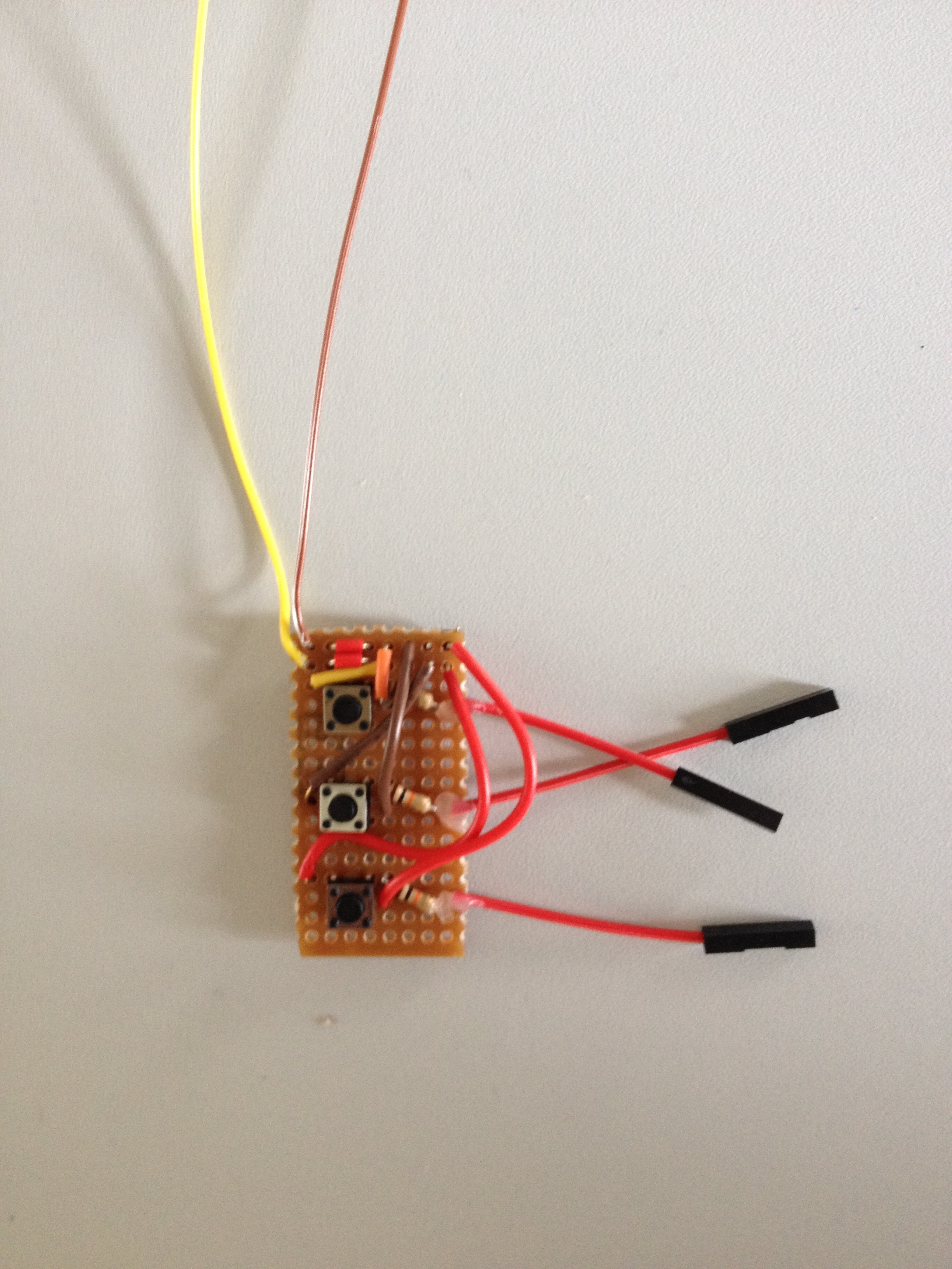
Complete array with ground and 5v attached.
After finishing most of the soldering the connections were tested with a multimeter to make sure they were all successful. Thankfully up to this point they were! I also removed the excess wire, glued the top to remove stress being placed on the soldered connection and sanded off the edges of the strip-board so they wouldn’t hurt the user or tear the fabric of the hoodie.
Stage 3 – Fabrication
The next step would be the hardest – constructing the circuit I would be using by sewing conductive thread into the hoodie (so it would appear not that much different from an ordinary hoodie, and if one was so inclined could print patterns over the top of it) and attached wires with male tops and fabricating them in place. It would also be a huge test in my none-existent craft skills, in that, I would have to learn how to use a sewing machine in order to accomplish the task. After a week long hunt to find a sewing machine I could use, plus someone who would be willing to teach me how to sew (another computational arts student – Matilda) I began what would be 18 hour ordeal of Alex vs. thread vs. fabric.
The circuit I designed as the template for the conductive thread was as follows:

The circuit in bread board layout

The circuit schematics
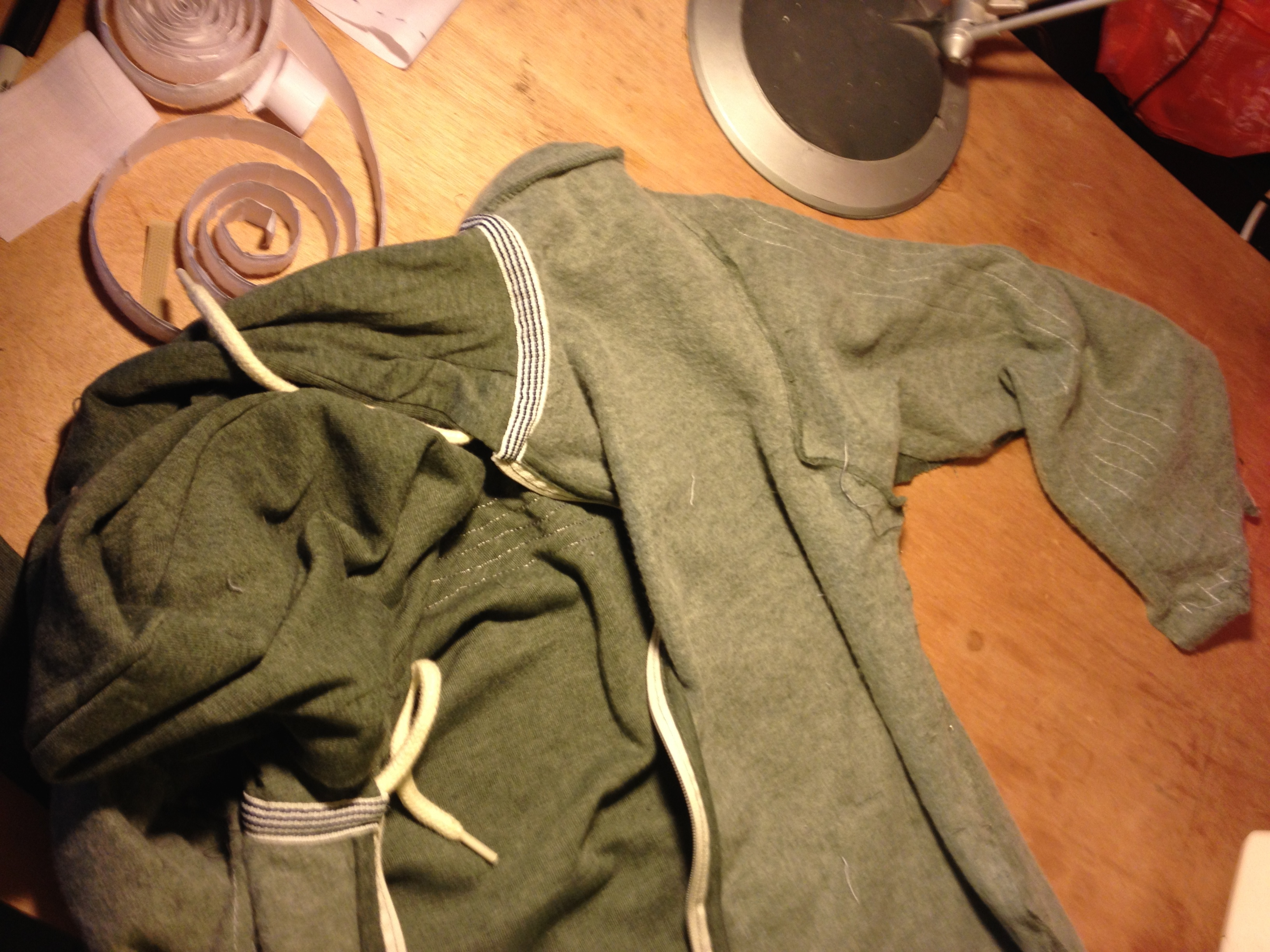
Before I could sew the conductive thread into the hoodie I first had to separate it out into segments that would allow me fit in into the machine, as well as, to stop me sewing together two sides of the hoodie (something which unfortunately happened a couple of times with the hood. To do this I took a knife down all the seams and cut the existing thread holding the hoodie together. Once I’d done this and after I had been given a run-through on how to use the machine I began to sew, making sure I didn’t break the thread (this happened a few times and I had to pull it out and restart) and more importantly, in terms of electronics, that I didn’t stitch over previous conductive threads. If I did this, there would be potential for the circuit to short! Another danger that I avoided at this stage was the danger of shorting the circuit via the skin contact of the user in the hoodie. I got around this by wisely stitching the hoodie inside, which placed the conductive thread on the outside of the hoodie. This way I wouldn’t have to worry about waxing it and the dangers of shorting it.

Cutting the seams of the hoodie.
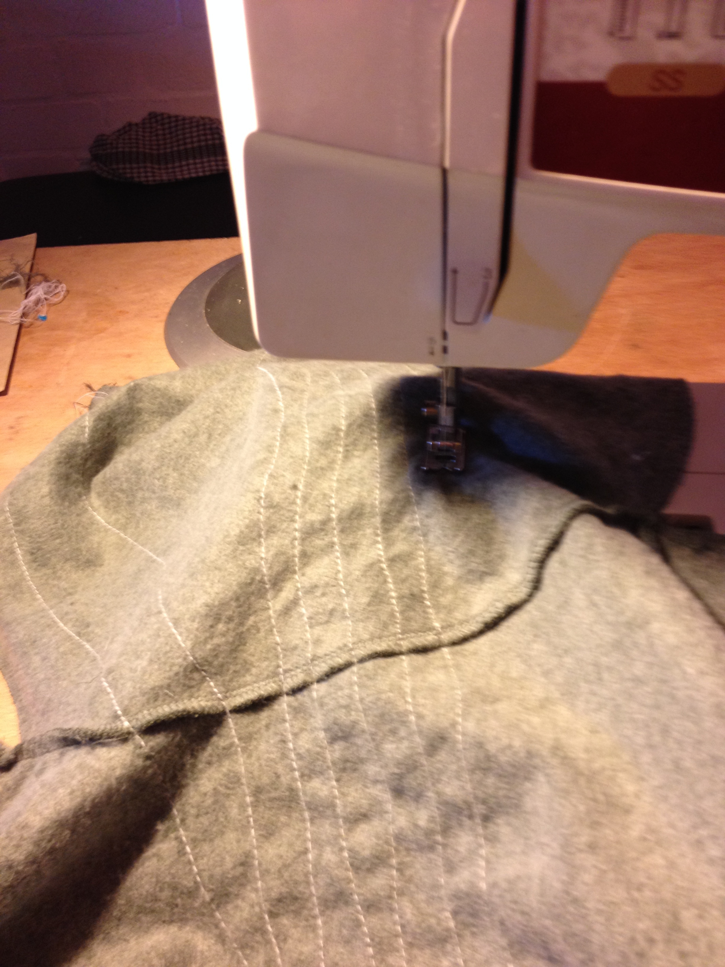
Sewing the thread along one of the sleeves

Close-up of the thread.
In-side-out sewing!
After I’d sewn the conductive thread through and sewn the hoodie back up I used some additional white cotton fabric to make coverings for the different component boards, placed velcro pads around the wrists and inside the front pocket so they could attached at will.
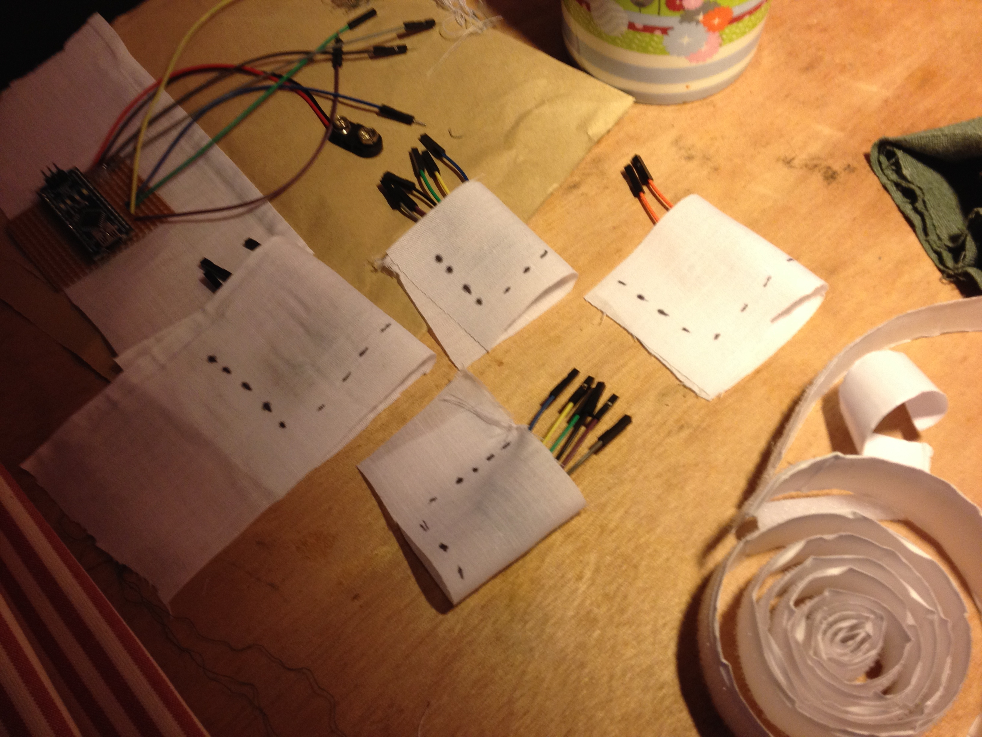
Fabric coverings for components waiting to be sewn and cut.
Once the coverings were sewn, and the velcro applied the next step would be to connect the ends of the thread to wires with a male end so they could easily slot into the components ends. It would be at this stage disaster would start to rear its ugly head.
Despite several claims the thread could be soldered on to, it proved very difficult to get it to purchase with the solder. With great perseverance i was able to get a fragile connection, however they proved to be prone to breaking. In an attempt to stop this, I incased the connecting point in glue, holding it in place.
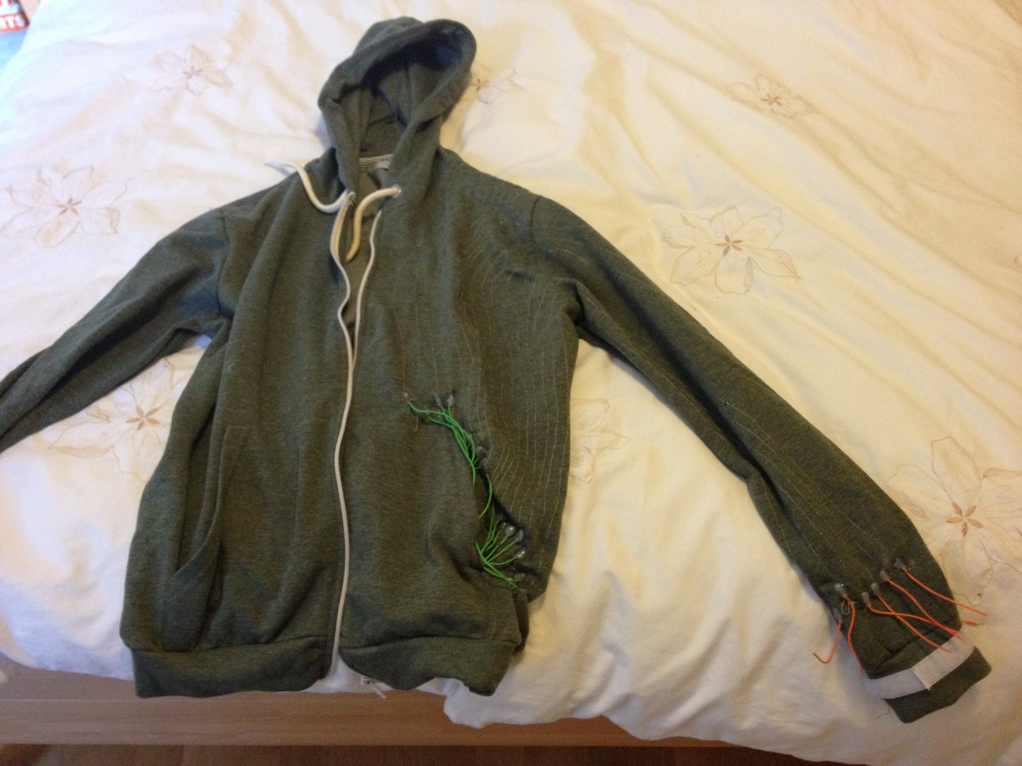
Shot of the hoodie post fabrication.

Right arm post fabrication, accelerometer on top, buttons below.

Left arm post fabrication.
Unfortunately it would be at this point things started to go really downhill. After plugging it all in and running a sketch on the Arduino it appeared there was no input from both the accelerometers and the push buttons. Several quick tests with a multimeter later and the problem seemed to be either no current at all or not enough/fluctuating levels. Testing it at several different points at different lengths, it appeared to not work at all as planned.
After consultation and inquiring around on the web, several plausible reasons as to why it didn’t work cropped up. Either the thread was too thin for the distance, plus additional stress points where it was stitched over the seams were causing problems, the hoodie material itself too thick and was possibly damping the current or the threading in parts were too close to each other causing them to short.
Regardless of why, the bottom line was that it still wasn’t working.
Stage 4 – Think again, time for software
By this stage frustration had set in so I decided I would take a step back from fabricating the hoodie and apply my focus on getting the principle behind my design and brief working. If I could have a working circuit I would at least know the basic project idea was sound.
After constructing the circuit as outlined in the above section – which I promptly tested, and gave the seal of approval to. I set about looking my different options for generating audio out. During the design stage/whilst I was waiting for parts I had explored the idea of using Mozzi. However during this period of experimentation I was never able to perform any complex tasks using it. Considering I had suffered a major set back regarding the conductive thread I decided it would be best to avoid another blow and settled on using the more familiar software – Cycling 74s Max.

Successful circuit layout test
In order to get the Arduino to talk to Max I used ‘Arduino4Max‘ by Daniel Jolliffe. Which comprises of the following code:
/*

* Arduino2Max

* Send pin values from Arduino to MAX/MSP

*

* Arduino2Max.pde

* ------------

* This version: .5, November 29, 2010

* ------------

* Copyleft: use as you like

* by Daniel Jolliffe

* Based on a sketch and patch by Thomas Ouellet Fredericks tof.danslchamp.org

*

*/
int x = 0; // a place to hold pin values
int ledpin = 13;
void setup()
{
Serial.begin(115200); // 115200 is the default Arduino Bluetooth speed
digitalWrite(13,HIGH); ///startup blink
delay(600);
digitalWrite(13,LOW);
pinMode(13,INPUT);
}
void loop()
{
if (Serial.available() > 0){ // Check serial buffer for characters
if (Serial.read() == ‘r’) { // If an ‘r’ is received then read the pins
for (int pin= 0; pin<=5; pin++){ // Read and send analog pins 0-5
x = analogRead(pin);
sendValue (x);
}
for (int pin= 2; pin<=13; pin++){ // Read and send digital pins 2-13
x = digitalRead(pin);
sendValue (x);
}
Serial.println(); // Send a carriage returnt to mark end of pin data.
delay (5); // add a delay to prevent crashing/overloading of the serial port
}
}
}
void sendValue (int x){ // function to send the pin value followed by a “space”.
Serial.print(x);
Serial.write(32);
}
Thankfully this worked straight of the bat I was able to start putting together the max patch. Scaling the values from the accelerometers I was able to use it to draw crude/albeit sometimes glitch waveforms. To begin with I had set a rather high resolution, in terms of how many steps each axis was split across by it’s force value. This resulted in some rather meaningless correlation between movement and waveform shape, which was in fact, the complete opposite of the desired result. By lowering the resolution; lowering the split points across each input force, the results began to sound better.
It would also be at this point that I discovered that using accelerometers was not the most useful way of data capture in terms of placing movement within a set space. This is due to them only capturing proper acceleration. Consequently I had to scrap how I hoped to sequence and manipulate the stored sequences and settle for constructing purely a live performance tool instead; allowing the use of three drawn then stored waveforms, pitch, gain and master on/off controls. The resulting Max patch can be seen in the image below and found in the zip folder of this project here.

The Max patch for the hoodie.
A short video example of the patch working with the breadboard based layout can be found below.
After getting results on the small breadboard layout I decided to have one more try on getting it work in hoodie form. Ignoring the conductive thread I opted for the lo-fi wired method, soldering wires to push button arrays and using a large loom to connect the components together. Unfortunately the combination of my un-dextrous self (complete with fracture thumb on my choice hand) and attempting to solder with an iron past its best proved to be deadly for the hoodie and the result soldering wasn’t effective and made a mess of push button components, and was possibly the cause of the Arduino Nano no longer booting any code. The only other alternative option I have to get it to work would be to use the larger Uno board, but unfortunately the loom of ribbon cable would not stay in either the Uno or the components, even with heavy duty tape.

Why don’t you work!
Stage 6 – *Wear* next
Despite the project not really working as intended, or at all, in terms of the end goal of the brief (The lack of a wearable synthesiser for one thing!) I still believe the concept is sound, and is in fact, could be a really popular commercial product. The criteria I set at the beginning in the brief could definitely be reached given more time (a 5 week period, especially with 2 weeks waiting for parts really pushed it), a bigger budget (someone else fronting the bill!) especially if the fabrication process could be farmed out to specialists. The last point being the most important; I had never sewn before, nor soldered (all my previous Arduino project involved masses of duct tape!) and it isn’t a skill set I feel confident in using, least not when I am limited on parts and can’t make mistakes. However in terms of concept, design solutions and coding I feel much more comfortable, and will pursue the project further beyond the module.